JMRI Sensor Setting

As part of my attempt to get my head round the workings of JMRI I have put together several simple layouts on which to test the working of sensors, turnouts etc.. I often need to set all the sensors to the INACTIVE state at startup and have found a simple way of doing just that using a Jython script.

[code language=”Java”]
”’
Start of Day Routine
~~~~~~~~~~~~~~~~~~~~
Sets all sensors to INACTIVE
”’

import jarray
import jmri

class SoD(jmri.jmrit.automat.AbstractAutomaton) :
def init(self):
self.sen = sensors.getSystemNameList()

def handle(self):
print "Setting sensors INACTIVE"
for s in self.sen:
print s
sensors.provideSensor(s).setState(INACTIVE)
return 0 # one shot, do not loop

SoD().start()
[/code]

Hello again!

I know… it’s been a very long time since I last posted anything here.
Most things have taken a back seat for some time as I have had to have an operation to see off a nasty medical problem. Things are far better now and I intend to get back to serious railway modelling. My friend Rob Ogden and I have joined the Manchester Mode Railway Society (MMRS) and are both getting involved with things there. In particular I have been recruited to the Slattocks Junction team to work on the control system on that club layout. For my sins I have been tasked with getting JMRI to work. I’m having to do a lot of reading and experimenting. Anything useful I’ll try to post here.

Decoder problems

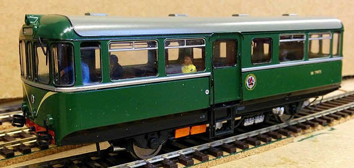
Oh dear! I’ve had some problems getting my nice shiny new railbus to work with a DCC decoder.

Getting access to the 21-pin socket in the roof of the model was not too difficult; it just needed determination, care and a couple pieces of plasicard. The problem arose when I plugged the decoder in. The engine would not run; it ran very smoothly using DC but there was no movement or sound when the decoder was fitted.

At first I thought that the decoder was faulty but quickly dismissed that theory when I fitted it into another loco and everything worked perfectly. I then tried fitting a known working 21-pin decoder in the railbus but still would not run. It didn’t make any sense to me as DC operation was OK with the blanking plate fitted. I contacted Tim at Arcadia Model Shop in Shaw where the loco had come from. He said that he didn’t know of any problems but offered replace it for me.

I had some further thoughts about the problem and came to the conclusion that  the only explanation was that that the track pickups and motor drive connections had been reversed. The decoder is fitted to a 21-pin socket on a small PCB that has eight small sockets on it. Some of those sockets have fine plug-ended leads connected to them.

railcar dcc pcb

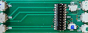
After some careful experimenting (the wires are very fine and only just reach the sockets in some cases) I found that the plugs in sockets CN5 and CN9 had been reversed. It was a bit if a stretch to get the plugs in the correct sockets as some of the wires had been kept as short as possible do to space constraints in the roof space but I managed to tease them out, refitted the PCB in the roof and installed the sound decoder again. Success! This time it all worked perfectly.

I have contacted Tim and let him know that I don’t need a replacement loco. I gave him the details of the factory assembly fault so that he can pass it back to Heljan. It does look as if they only test run the locos with the DC plate fitted and assume that all will be well when as DCC chip it fitted in it’s place.

The next job is to fit the speaker in a suitable position in the saloon where it won’t be too obtrusive. I think I’ll leave that for another day.

JMRI sensors and turnouts

I’m still a novice when it comes to JMRI. It is a really powerful bit of software but lacks a bit when it comes to documentation. This is especially so in the area of scripting. Still… more of that later.
A simple way of regarding the inputs and outputs that JMRI uses is to regard all inputs as sensors and all outputs as turnouts (points). It’s a simple terminology but easy to get ones head round.
On Key Hernan most of the inputs are TOTI sensors that report whether a section of track is occupied or not. It does this by sensing traction current is being taken by a section of track. This is usually because a locomotive is in the section. Other sensors could be press buttons or switches on a control panel. The turnouts can be actual turnout mechanisms (servos or solenoids) or signals, level crossing gates etc.; in fact almost anything that needs to be physically moved.

The Grand Tour

Having managed to understand JMRI sensors and turnouts I have now set to and written my first big script. I’ve called it the Grand Tour as it runs an engine from the bay platform around the layout visiting every section of track and crossing every point (turnout). To be truthful it is a rewriting of a sample script in the JMRI documentation but it is heavily rewritten.
You can see the script here.

Power up!

Today I managed to get all the power feeds installed via the TOTI units along with the servos for the point controls.
To install the servos I used the FCU to set the servo to the mid position, jammed the point switch blades to the mid position then screwed the servo mount down. It was then fairly easy to set the servo movement limits using the FCU again. The fiddly bit was setting the position of the microswitches on the servo mounts. The microswitches are used to control the polarity of the switch blades as the point changes position. It’s worth the trouble of fitting them as it helps to prevent electrical continuity problems if the swtich blades don’t make good contact with the stock rails.
The TOTIs worked perfectly and were feeding back track occupancy information to the JMRI control system.
It all seems to be working OK and a test run went OK.

A more complex script

I have written a more complex script that uses track circuit sensors to detect the locomotive position and then operates points and loco speed and direction. Sound effects are also controlled by the script. This video show the script running. In the video you will see the JMRI Sensor table status, the dynamic track diagram and the output of the script.

You will be able to see the contents of the smaller windows if you play this video in full screen mode.

My first script

I have spent most of today after repairing a bit of damaged track, writing a script. It was an exercise in JMRI scripting and has enabled me to learn a lot about sensors, turnouts and delays. You can view the script here. It’s not very clever but it is mine own.